Develop technology and tools are in Design Automation for Power Electronics
Preface
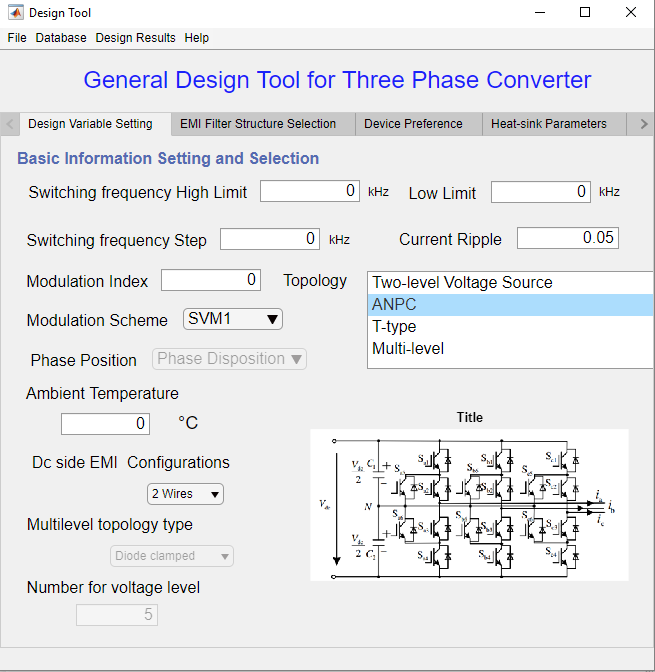
The blog is built for recording the development of the tool for Design Automation in Power Electronics. Also, it can be used as a User’s Guide for the design tool. The design tool covers the following topologies at three-phase motor drive application:
- Three-phase two-level voltage source converter
- Active neutral-point-clamped converter
- T-type converter
- Multi-level diode-clamped converter
- Multi-level flying-cap-clamped converter
Platform
The whole design tool is designed and built in MATLAB appdesigner, and it requires the installation of a Simulink module for operation. The tool is designed based on the concept of Model-View-Controller (MVC).
 The UI frame, design iterations and models are programmed separately for easy implementation and updates.
Features
- All models are created with different functions
- Design iterations are written with separate M files
- UI interface is built with Appdesigner
- Optimation algorithms (or searching algorithm) are employed
- To reduce execution time, switching function based equivalent circuits are adopted to replace switch-based simulations.
- Employ advanced physical models of magnetics and devices for accurate design and prediction
- Specialized for three-phase dc-fed motor drive design
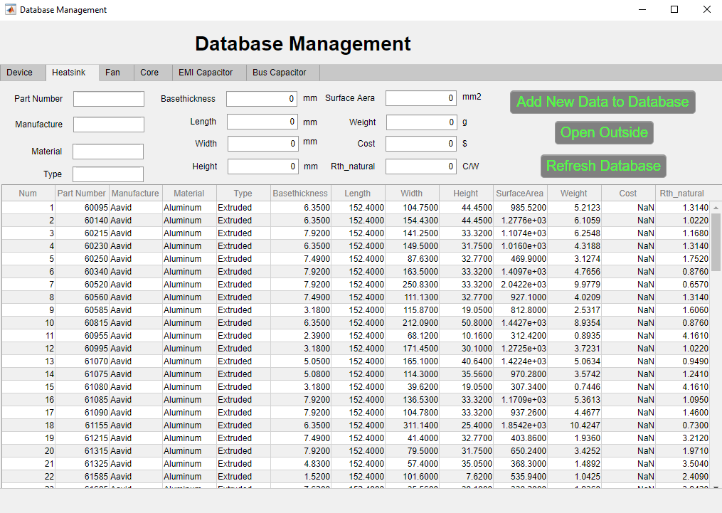
- Includes device, heatsink, fan, magnetic core, capacitor database
Functions
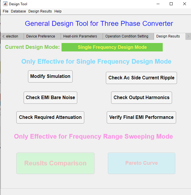
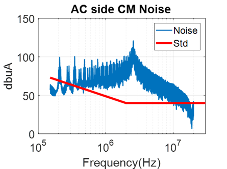
EMI filter design optimization
 The EMI filter supports either single stage or two stage designs. Based on bare noise from simulation, the corner frequency will be calculated to decide to filter element electrical values. In order to get the best L and C combination in a specific corner frequency, PSO optimization algorithm is employed to search the case with the lowest weight.
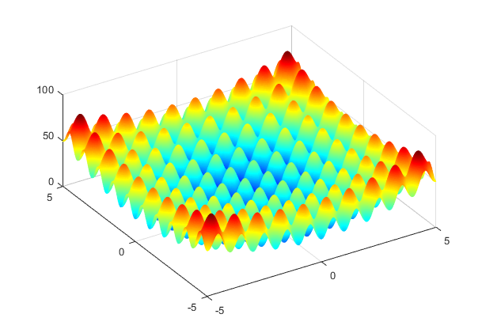
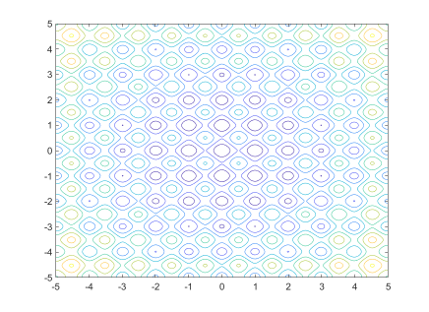 The most difficult part of EMI design is the gap between the prediction of paper design and the real EMI testing results.
To reduce trial and error experience in EMI filter design, more advanced physical models are employed to accurate predict the attentuation of the designed filter. E.g., dc-bias dependent permeability in the powder core and frequency dependent permeability.


Database management
Provide database management for device, heatsink, fan, magnetic cores, EMI capcitor and bus capacitor
Design results look up
Look up design results from design results history
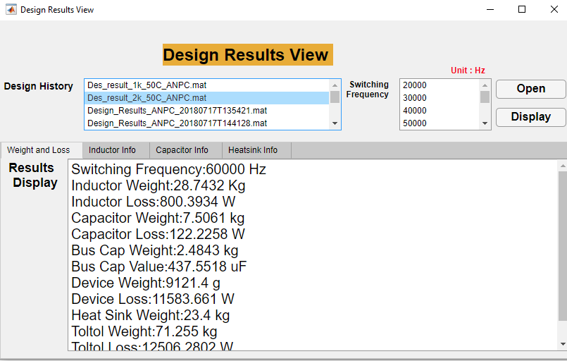
- Weight
- Efficiency
- EMI design results
- Heatsink design results
- Core selection information
- Capacitor selection information
- Loss breakdown
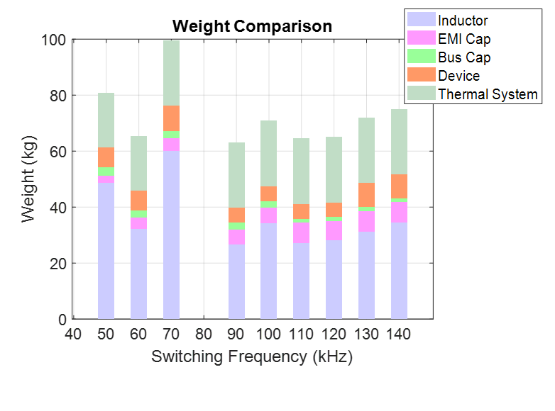
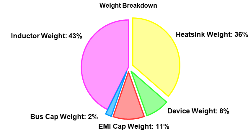
- Weight breakdown
- Switching freuqency sweeping
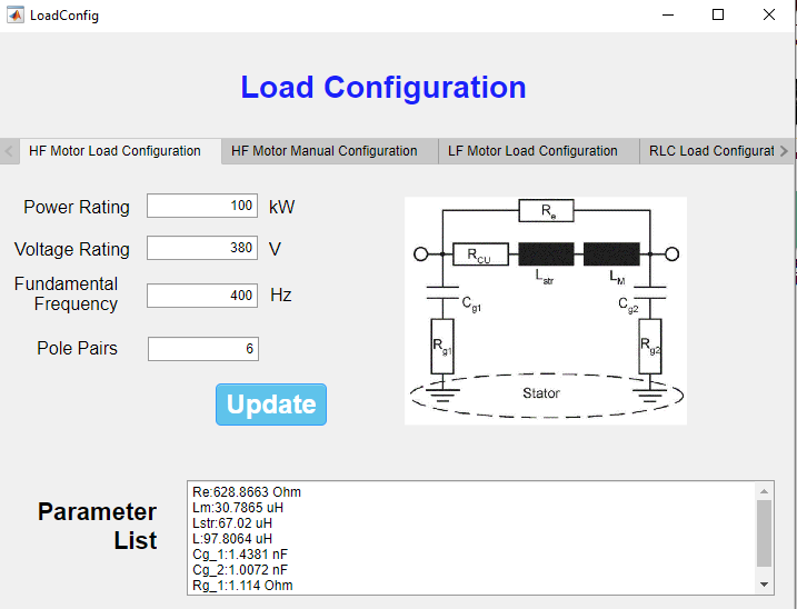
Load configuration
- High frequency motor model for EMI prediction
- Low frequency motor model for THD prediction
- RLC load
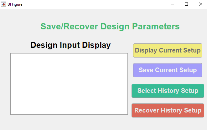
Design input parameters manangement
More will come out
More detailed information will come out in this blog. Thanks!